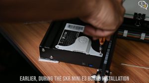
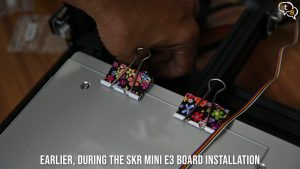
I’ve had the Skr Mini E3 and the BL-Touch lying in my room since January, as I had installed the Skr Mini board into my 3D printer earlier, the time has come to install the BL-Touch to the printer. So, let’s get started.
The steps in this video are more for the SKR mini E3 and to a limit to the Creality 3D controller board.
But the final wiring is a bit different on the Creality board, so would recommend looking for a custom tutorial video.
Now that, that’s out of the way let’s get started with the installation of the BL-Touch. I’ve watched umpteen tutorials on the steps to install the BL-Touch, and they do get confusing at times, making the task look more daunting than it really is.
This video is a straightforward install with the firmware available on the git repository directly for download without the need for compiling. I agree, it won’t be the latest version but at least the steps are easier to follow, and you can upgrade the firmware to the newer one, once it’s available.
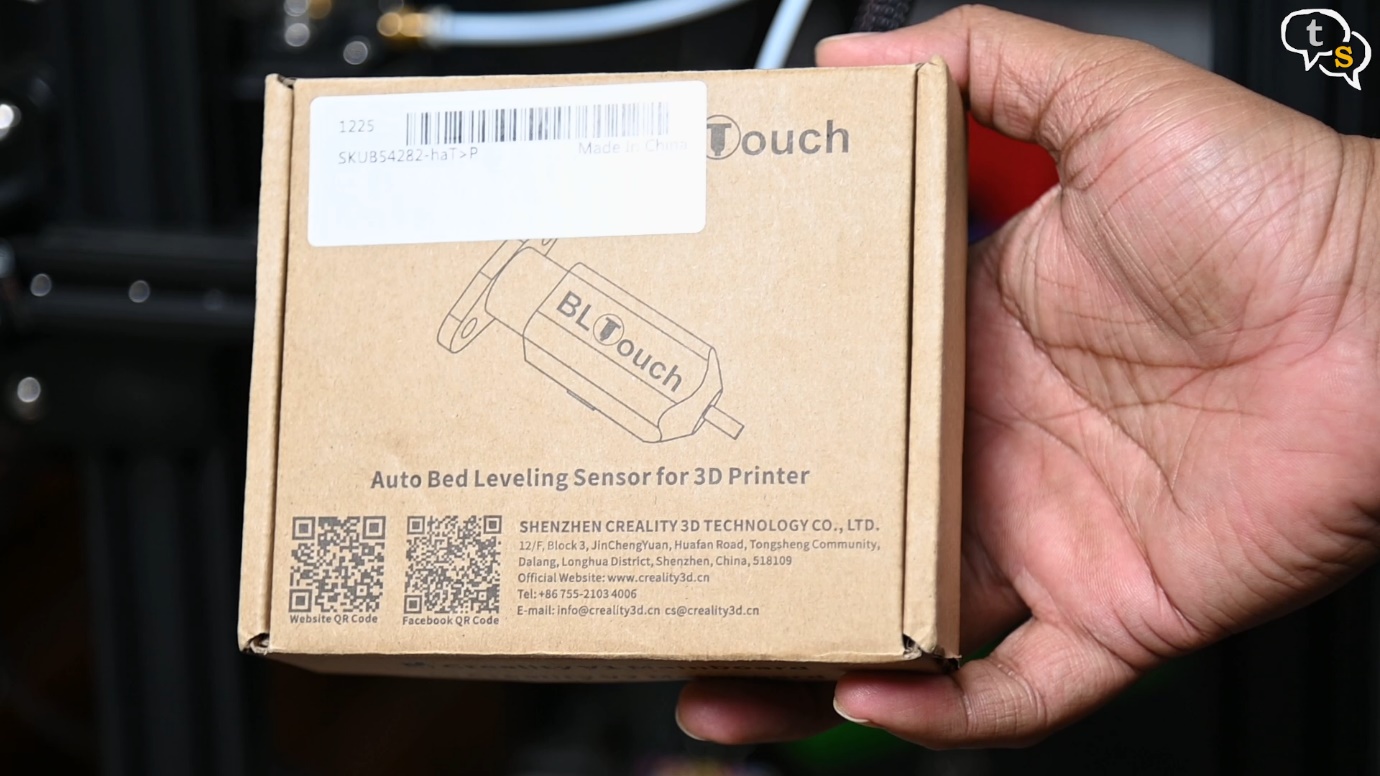
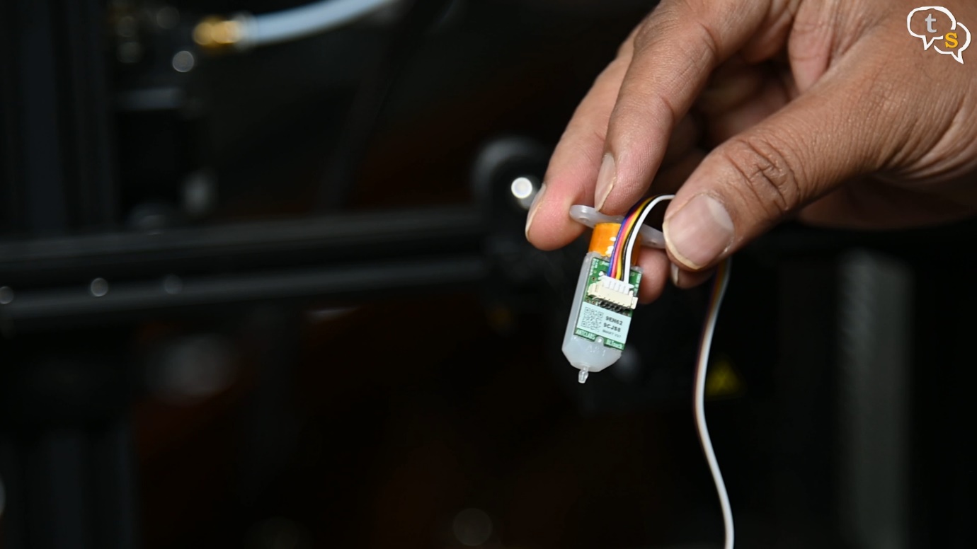
The BL-Touch is a high precision auto levelling solenoid and hall sensor which can precisely measure the tilt of the bed surface. It works on any kind of printing bed, such as glass, wood, metal and so on.
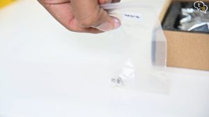
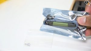

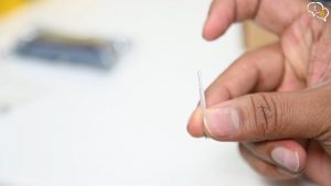
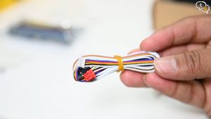
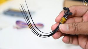
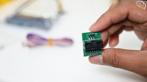
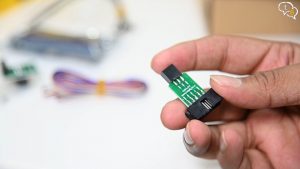
Opening up the box we have included screws, Burner which I will not be using, Bl-Touch sensor with an additional probe, this is the BL-touch 3.1, Connectors, Zip ties Pin Board, ISP pin board, Frame
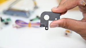
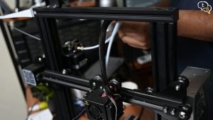
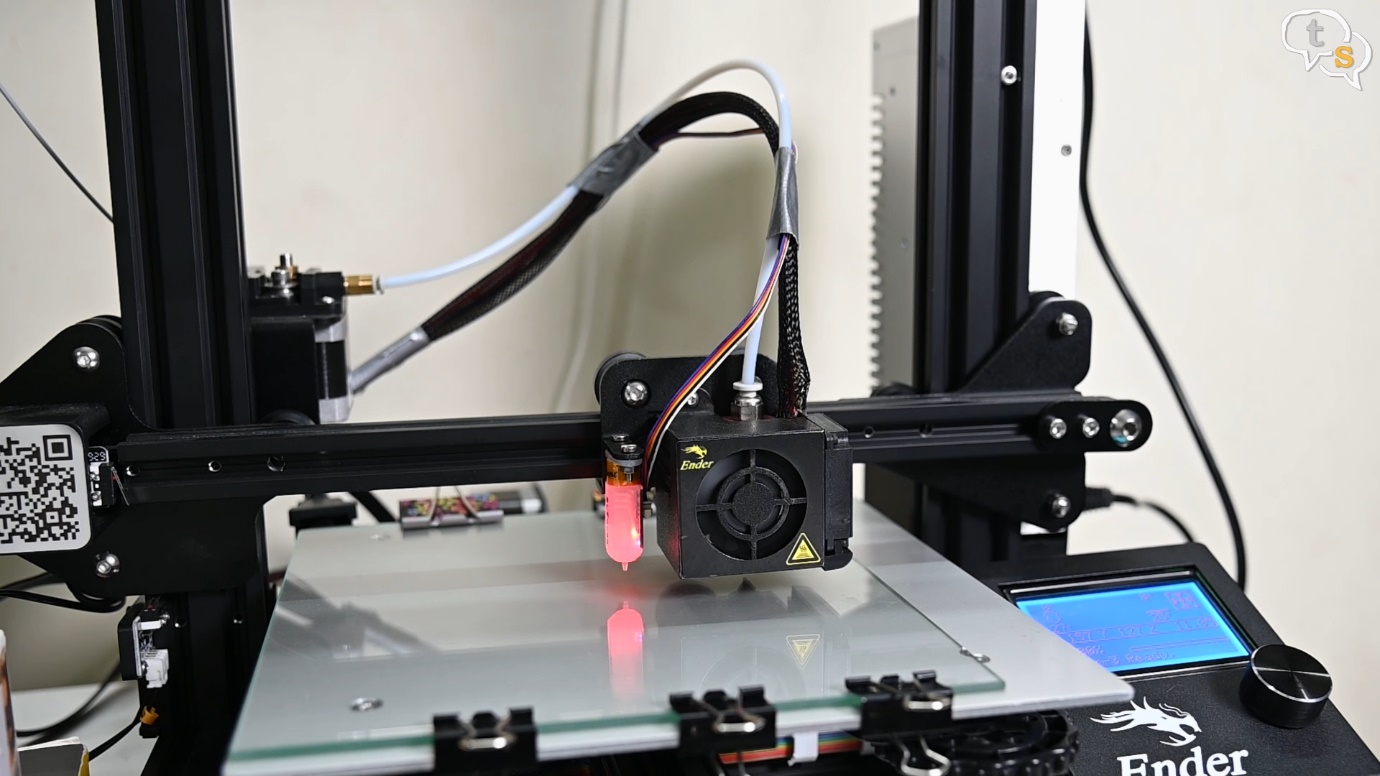
We need to install the sensor in line with the extruder, which is possible with the provided frame.
I’m going to be installing the sensor here. The screw holes and bolt hole match up and being part of the kit you don’t need to print one anymore.
The frame is also metal, which will be sturdier than PLA anyway.
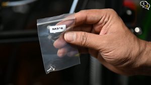
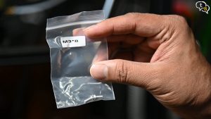
We are provided M3x6 and M3X8 which are 6mm and 8mm M3 screws. These will be used to fasten the sensor to the frame.
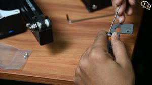
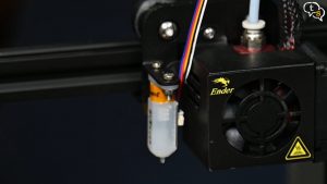
Before we install the frame to the printer, we mount the sensor on it. Use the screws provided to mount the sensor, this is how it looks, the connectors on the sensor point towards the length of the frame.
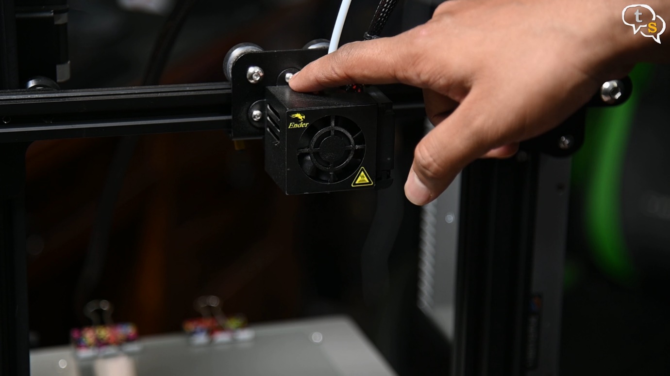
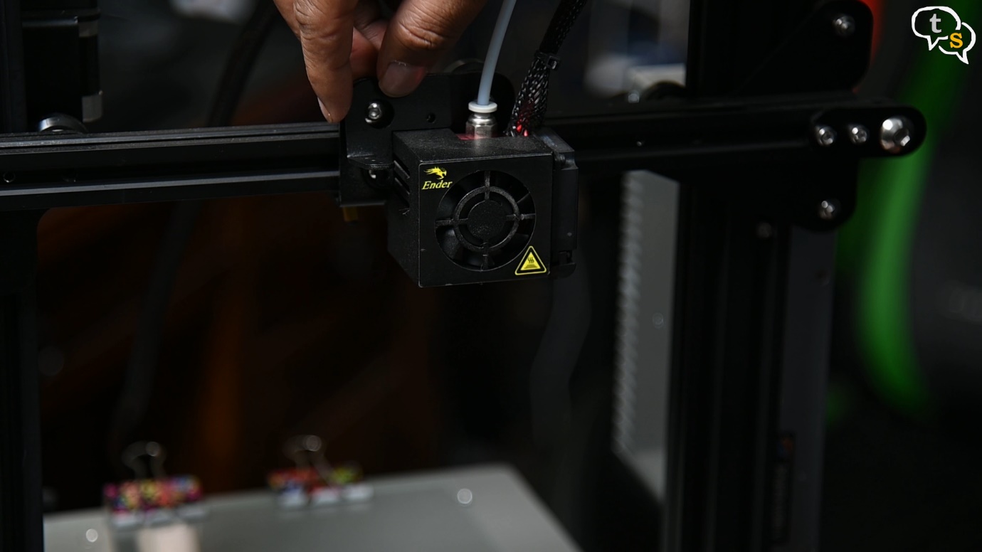
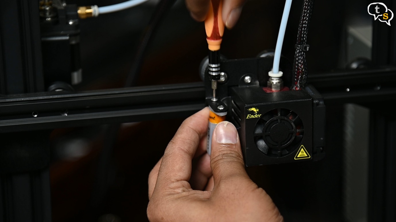
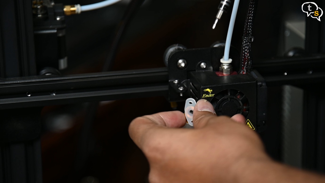
Now we need to get the cover off the extruder and fan. Once the screws are removed the cover pops off like this.
Place the frame on the mount, aligning the screw holes, and tighten the screws to fix in place.
Before attaching the sensor to the frame, I insert the connector into the BL-touch. Make sure of the direction before inserting.
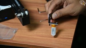
I found that the threads on the BL-Touch were not being held up by the screws and it kept falling.
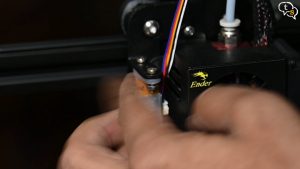
I then rummaged through my son’s electronics kit and mounted the BL-touch using a screw and nut instead, which held the sensor in place so much better.
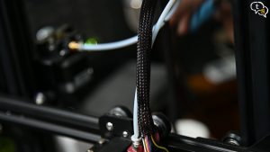
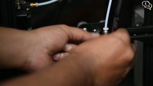
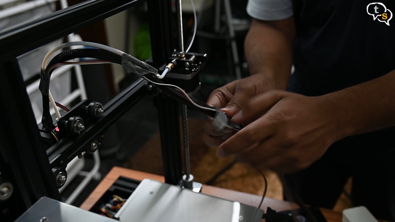
Next, we cut the zip ties holding down the wire sheath, and snake the sensor wires all the way down to the main controller board. It’s quite a big job, so instead I ran the wire externally instead, but if you have the patience you can do it the right clean way.
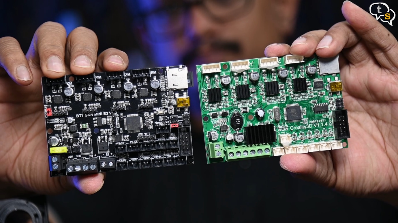
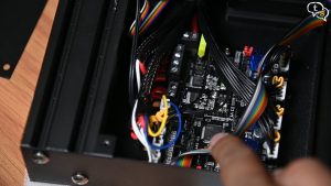
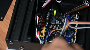
Now to install the sensor wires onto the main controller board. We need to take the top cover off as we had done earlier. Two screws in the front and one in the rear.
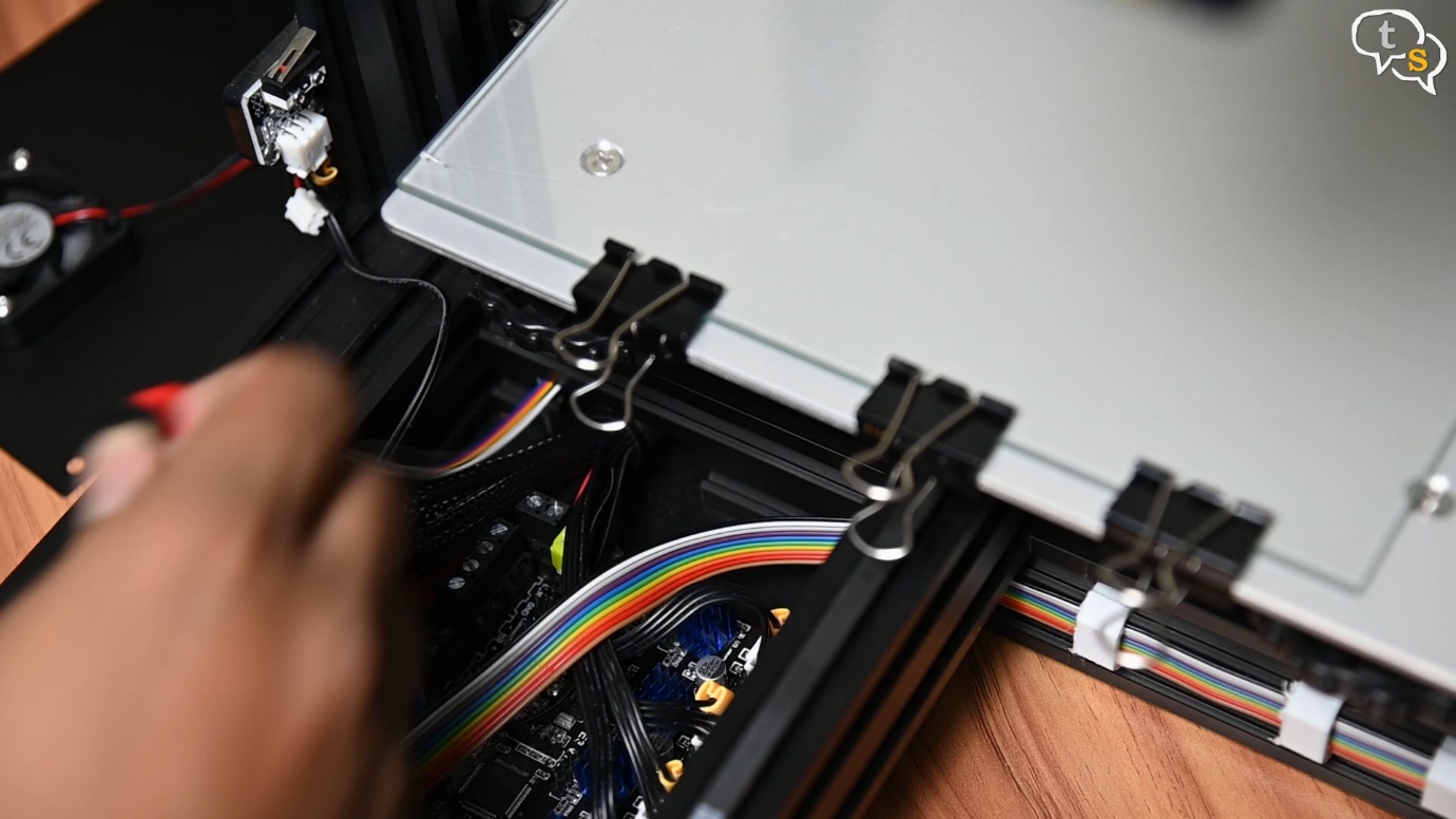
Pull in the sensor wire from the hole in the bottom to the front over the motherboard. Here they are, the power and z stop connectors.
Being the SKR board we don’t use the ISP and Burner included, but you will need them if you’re using the original Creality board.
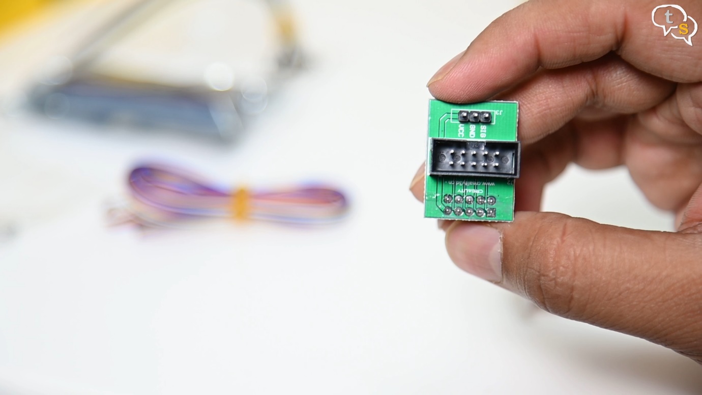
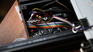
The best part is that we don’t even need to use the included pin 27 power adapter board as the SKR mini E3 has a dedicated Sensor port.
But there is one, not a problem but still an important step to take before connecting to the SKR board.
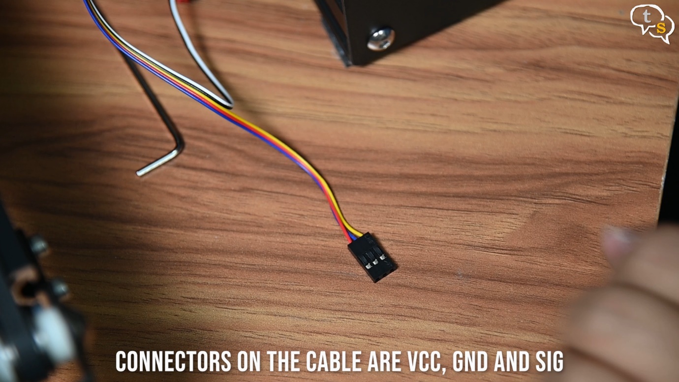
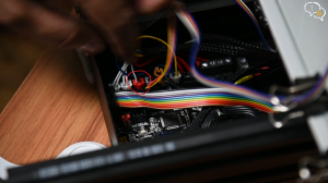
The connectors on the cable are at present Red, Blue and Yellow which are VCC, GND and SIG.
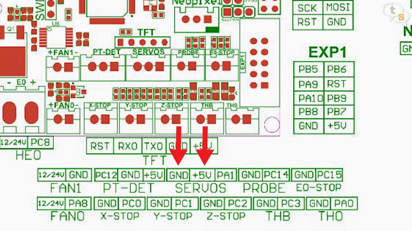
Looking at the diagram on the SKR board, the blue and red needs to be flipped to GND, VCC and SIG.
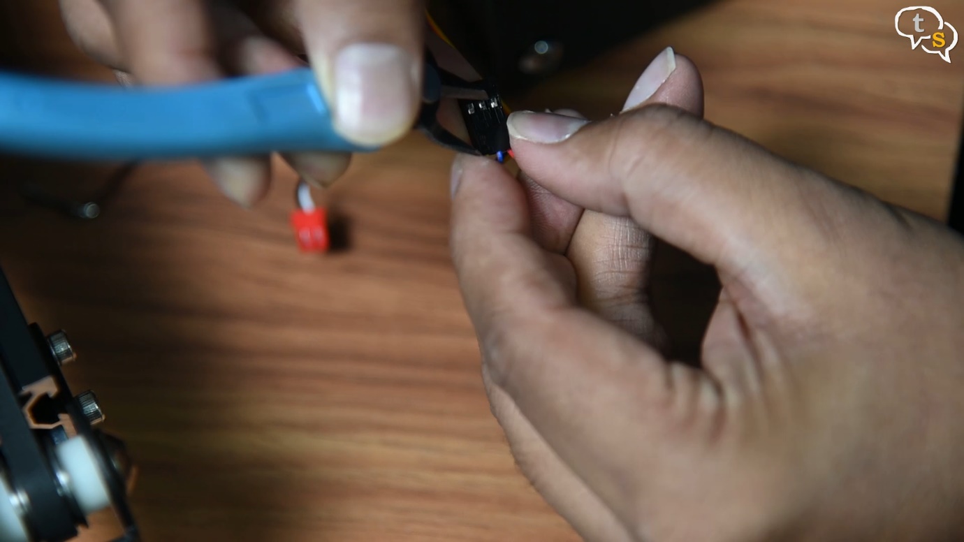
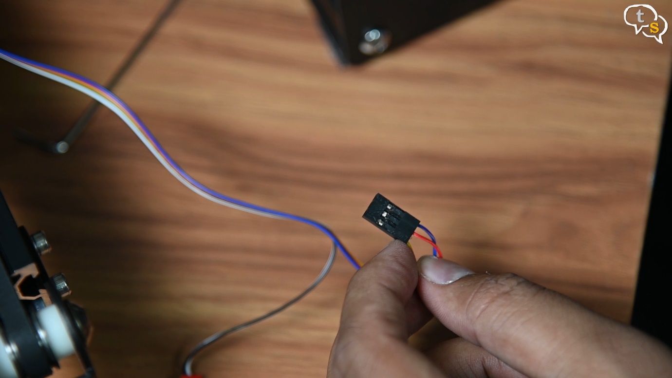
These being du-pont connectors, pry up the lugs and pull the connectors out. Once out, rearrange the wires into the correct slots and you should feel it clicking in, which indicates that the wires have locked in place.
Now insert the connector into the sensor plug, make sure to match the direction.
Also unplug the Z-stop connector and connect the one from the sensor. The sensor handles all the z-stops now.
As I didn’t snake the wire through the harness, I used duct tape to attach it externally all the way to the bottom.
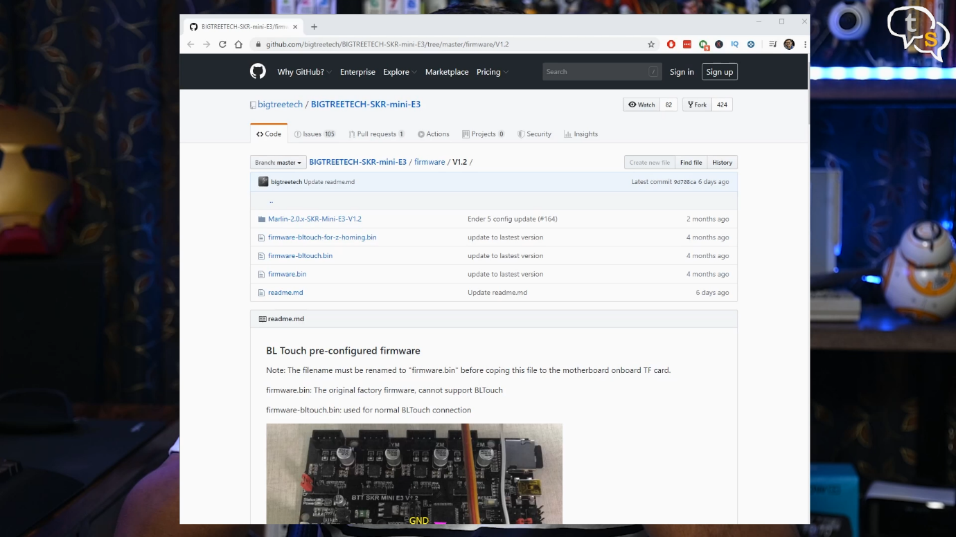
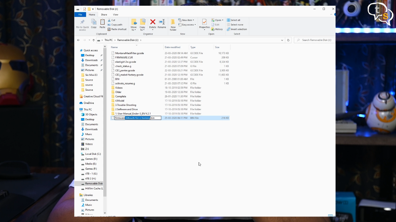
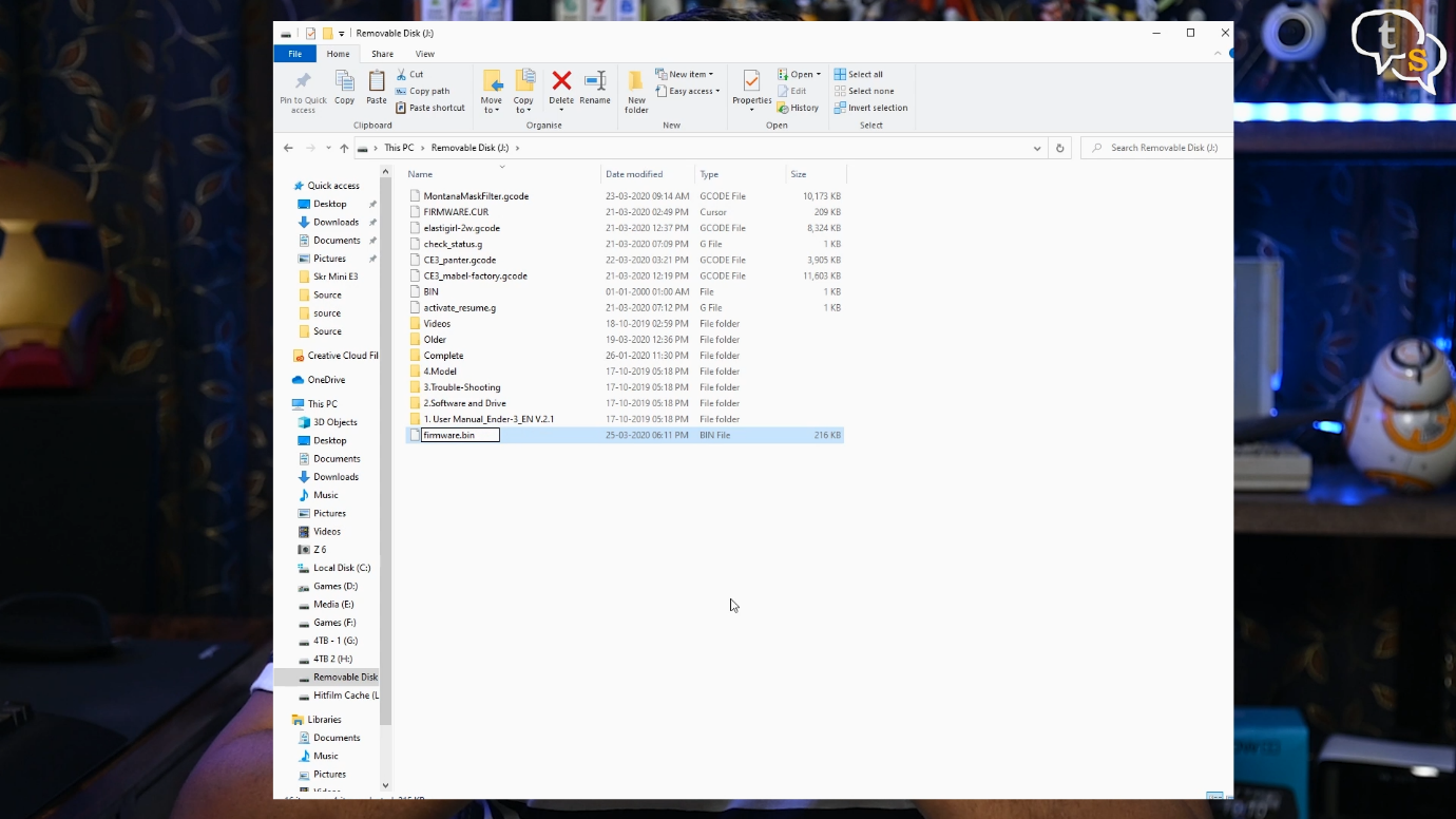
Now we need to flash the new firmware with the configuration for BL-touch present. So open up the SKR mini E3 git, download firmware-bltouch-for-z-homing.bin file, rename to firmware.bin and copy to the printers micro-SD card.
Make sure to download “firmware-bltouch-for-z-homing.bin” and not “firmware-bltouch.bin” as we don’t have a z-stop switch anymore, the extruder would start grinding at the corner. With the z-homing firmware, it will level itself at the center of the bed instead of the corner.
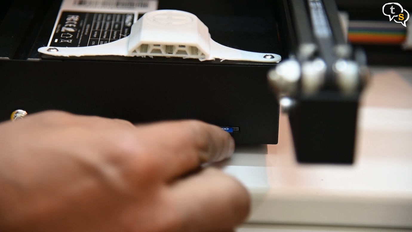
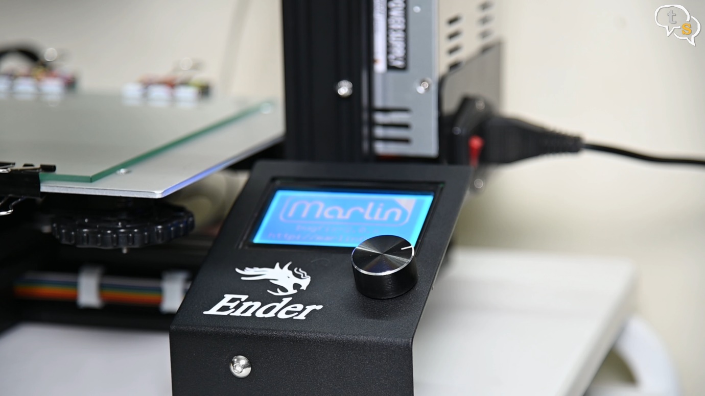
Insert the card into the printer’s microSD card slot. Turn the machine on and as it starts up, the firmware is flashed.
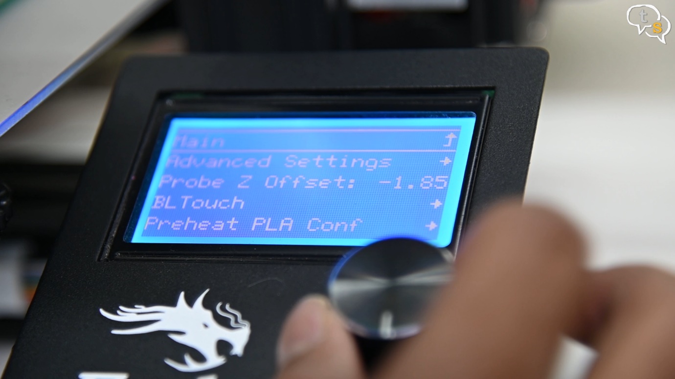
Now we are ready, you should notice a new BL-Touch option in the configuration menu.
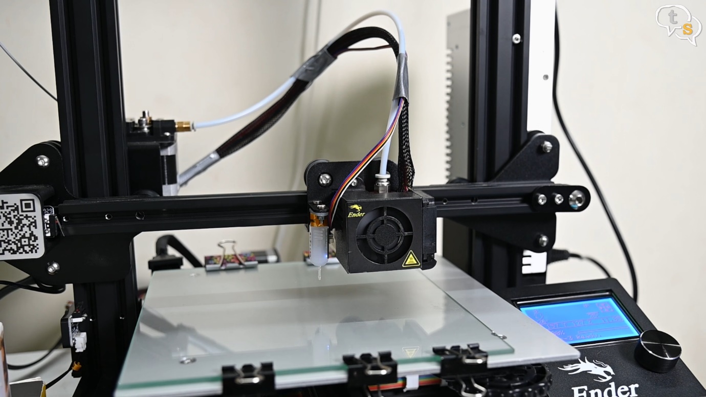
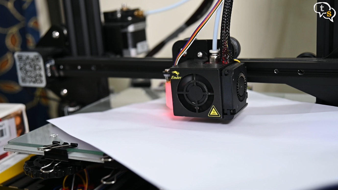
Let’s try auto homing the extruder. Well the moment of truth. The sensor is active, and the probe is deployed.
It touches the bed and stops the extruder from hitting the bed. Phew, that was close, as we don’t have a Z-Stop switch connected anymore.
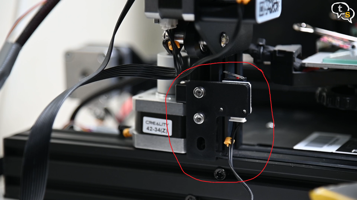
Now that we know it works we can remove the Z-Stop Switch completely.
On printing I find that the extruder is quite high, so I will need to calibrate the bed and the sensor z-offset to get it at the right height.
As with most installs, we need to do an initial bed calibration, which is done by making sure the extruder is the right height away from the bed to get the best smushing of the PLA for best adhesion and print.
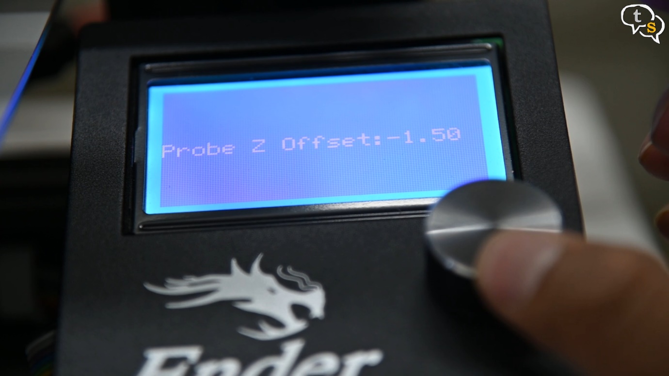
We also need to set the z-offset to get the height just right. I found the offset for my printer to be -2.96 and it’s working really well once I set it.
Well that’s how you install a BL-Touch on the SKR Mini E3, hope this helped you understand the steps and enabled you to install one yourself.
I can be messaged at tech@talkingstuff.net or WhatsApp us at 9652578833.
Thank You for checking out this tutorial and Happy 3D Printing.